Published
by Sebastiaan de Boodt - Manager Product Development
Advanced Electronics Solutions
Thermal management is one of the key design aspects for all electrical systems, as it has a direct link to reliability and lifetime of the system, both in the short and long term.
If an electrical system overheats critical components will start failing, leading to an instant system breakdown. For example, overtemperature in an IGBT junction caused by local overtemperature, insufficient cooling or overload can lead to direct destruction of the semiconductor.
In the long term, materials degrade related to excessive temperatures and will lose integrity or fail at a certain point. Materials tend to get brittle as high temperatures accelerate the cross linking of the material, taking out all flexibility of typical plastics. Performance busbars use PET (polyester) insulation rated 105°C, which has a long lifetime for typical traction applications (25 years @ 80°C). For extreme long lifetime or high temperature applications Thermal 130°C insulation is applied (40 years @ 100°C).
Although a busbar typically outperforms all other components in an inverter throughout its lifetime, insulation brittleness/cracking is the most common failure over a long lifetime that is dependent on operating conditions, which can lead to an electrical break down and system failure.
To assess the useful lifetime of a busbar it is important to understand the mission profile — the percentage of time at each temperature during operation. Knowing only peak temperatures will not allow you to correctly establish the lifetime of a busbar.
The maximum hot spot temperature is the combination of ambient temperature and component heating.
In this document, we will describe component heating or "thermal management."
For the long-term reliability of a system it is necessary to optimize the impact of generated heat Ploss (electrical loss) on the system hotspot temperature. The temperature in the hotspot can be referred as delta T (or ?T). The target of a correct heat management design is to minimize the value of delta T to maximize the lifetime of the system.
The relation between generated heat or loss Ploss per unit of outer surface A of the device and the consequent temperature rise (delta T) is the total thermal resistance Rt.
Ploss/A = Q thermal flux
Rt is also the sum of all thermal barriers from heat generation "inside system" to the "outside world."
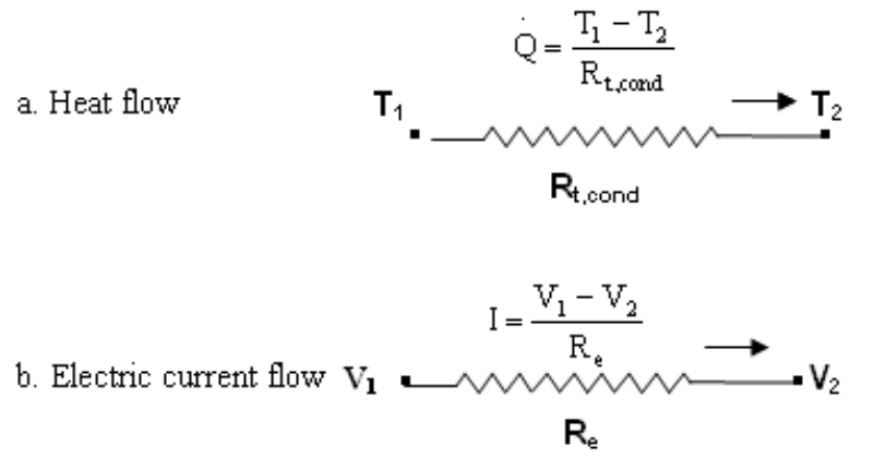
Q= △T/ Rt
The thermal flux Q is analogue to the current I in a system; an electrical current I generates a voltage drop V = V1-V2 across the electrical resistance Re.
Thermal equivalent: the thermal flux Q creates a temperature difference T = T1-T2 across a thermal resistance Rt.
For a given thermal flux Q, the higher the thermal resistance, the higher the delta T, and thus, the higher temperature in the hotspot.
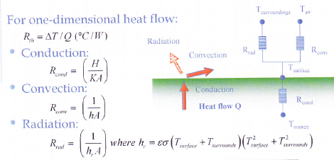
This thermal resistance to the ambient is typically composed by the three typical heat transfer modes:
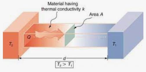
The thermal resistance Rth inside the system (conduction) is proportional to the averaged distance d to surface of the device, and inverse of the thermal conductivity K (W/mK) and surface A.
Rcond= d/K.A;
In case of a busbar, the heat is generated all over the conductor body and conducted to the outer surface. The distance d is the integrated distance over the complete busbar from each heat generating spot (= each segment in a current carrying conductor).
The higher the surface A or heat conductivity K, the lower the Thermal conductivity resistance Rcond.
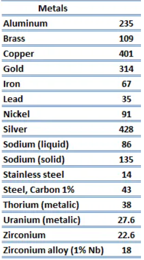
Metals have a very high thermal conductivity coefficient K: copper 370W/mK; aluminum 230W/mK.
This means that the temperature increase inside the busbar is not only low but it is also very well spread all over the busbar, reducing the impact of the hotspot.
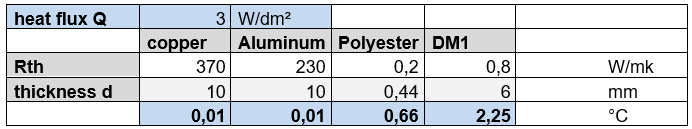
In this calculation model the temperature drop for a typical heat flux to the outer surface of a busbar of 3W/ dm² (delta T 30°C; h 10W/m²K) is calculated on four different materials with maximal busbar application thickness (in mm).
The temperature drop for a conductor is extremely low (<0,01°c); for insulation it is max 0,66W and for DM1 it is max 2,25W.
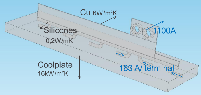
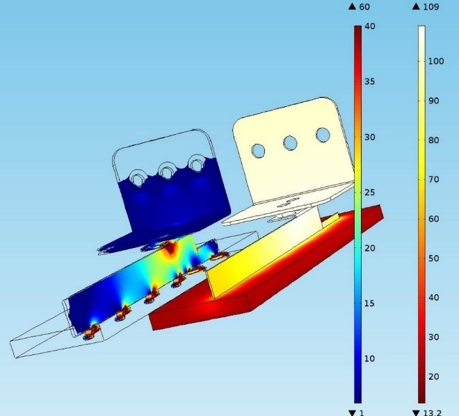
As an example, the current distribution in an small busbar + terminal inside a Primapack IGBT has very high local current densities (40A/mm²- typical 5A/mm²), leading to more uniform spread global heating (+89°C).
Thermal conductance Rcond is not dominant on the overall thermal resistance Rthe, as the power density (loss) is low, and the conductor has a high thermal conductance.
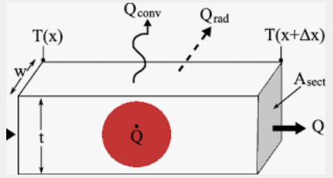
Once the heat reaches the outer cooling surface A, heat will be removed from the object through the outer cooling surface A by convective flux Qconv and radiative flux Qrad.
To minimize the heat rise, the thermal resistance Rt should not only be low, but the outer cooling surface A of the object should also be maximized.
In any electrical component, the total outer cooling surface should be maximized for a good heat removal. A ROLINX® busbar has a great advantage in this field, as its total surface is very large for its volume due to the flat and thin construction, and it can be optimized to maximize the outer cooling surface A.
For an IGBT module, where thermal losses are from another degree (KW range), the cooling surface is fixed and is not a design parameter. Only Rt can be affected by the cooling mode and the heatsink design to accommodate increased losses with a required system lifetime.
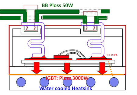
The heat dissipated in a medium-size busbar is in the 50W range, while the IGBT/SiC junction generates losses in the range of 1 to 5kW, which requires a different cooling mode. The optimal cooling mode is consequently directly related to the total dissipation and the allowable temperature rise.
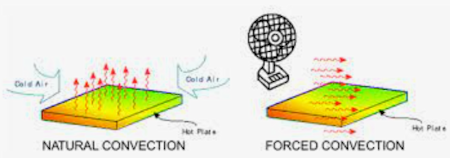
Typical cooling modes impacting on the outer surfaces with a typical heat flux Q are (this is removed heat P (W) divided by surface A (dm²)):
A typical example for busbar natural cooling is that the heat flux to ambient is rather limited and dissipation can be removed by natural convection. Total conduction loss is in the 10-100W (size dependent) range.
For a maximum temperature increase of 30°C, with the minimum heat transfer coefficient h of 20W/m²K (cooling to both outer surfaces), an average dissipation of 6W/dm² is allowed; a busbar of 25x 40cm² can easily dissipate 60W by natural air cooling. Busbars are most often designed in the assumption that there is only natural air cooling.
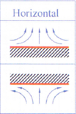
The heat transfer for natural cooling is sensitive to positioning, as natural convection is based on natural air circulation generated by geometry of set-up; cooling of the horizontal bottom is less efficient.
Horizontal busbar positioning versus vertical positioning creates a different natural convection flow. In the presented busbar set up for a power density of 8,5W/dm² (double sided higher than 6W/dm² nominal), the temperature rise is resp 42 and 37°C and the corresponding total heat transfer coefficient (double sided) horizontal vs vertical: 20W/m²K and 24W/m²K. The vertical position increases the total heat transfer coefficient with 20%. This heat transfer coefficient also includes radiation.
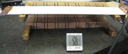
Figure 1: Busbar in horizontal position
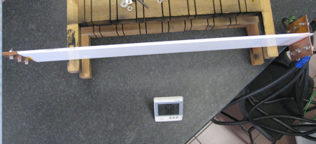
Figure 2: Busbar in vertical position
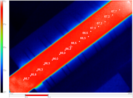
Figure 3: Temperature rise 42°C
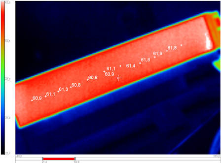
Figure 4: Temperature rise 37°C
A forced convection (by fan) can significantly increase the cooling/heat removal by a factor of 5 to 10, proportional to the increased heat transfer coefficient h (50..100W/m²K), allowing 2 to 3 times higher currents compared to natural cooling.
In a typical inverter system, some forced air is always cooling around the power stack, giving some additional cooling, removing a considerable amount of heat and creating additional operational temperature margin.
Due to the extreme high-power-loss density inside an IGBT/SiC module, forced water cooling is inevitable. The power rating of switching module is directly related to the max junction temperature: typically 125°C for Si and 175°C for SiC.
The lower the Rt, the higher the currents and power which can be converted. The allowed Ploss is directly inverse proportional to Rt: halving Rt means doubling the allowable losses for the same maximum temperature of the junction Tj.
If water cooling system is too complex (maintenance/cost) for some high power inverter systems/applications and the modules are cooled by air, the transferred power is reduced to 40% of rated power. The thermal resistance Rtha of the forced air heatsink is significantly higher than the heatsink to water resistance Rthw.
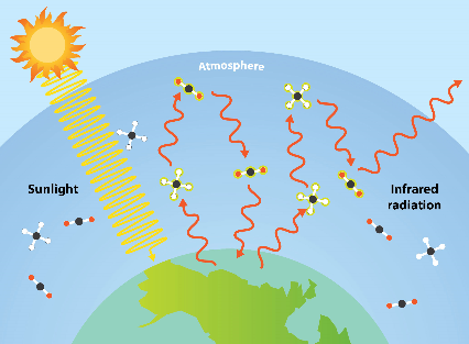
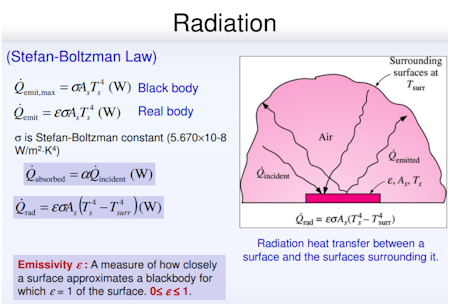
Radiation is commonly associated with the sun, where visible light (short waves) with heat (long waves, or infrared) is radiated to earth through vacuum.
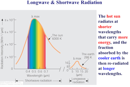
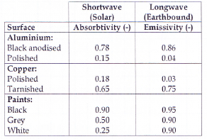
Black surfaces absorb heat (high absorbtivity – 0,9), while white and bright surfaces reflect the short waves (low absorbivity – 0,25).
Once touching earth these waves are reflected into ambient to spread the heat to cooler surfaces with longwave radiation, the so called infrared waves or radiation.
A "radiator" for inside house heating is the most common longwave radiation emittor, where heat not only is transferred through convection, but mainly by radiation. This is even more easily perceived in the outdoor IR heaters installed in some terraces during cold months.
Also, radiation occurs at lower temperatures between objects when having temperature differences according to the Boltzman Law. According to this law, heat radiation is proportional to the 4th power value of the temperature.
For longwave radiation there is almost no difference in emissivity ε between white and black surfaces (ε in range 0,9...0,95). Metals hardly radiate any heat (Alu, Cu: ε in range 0,04). This is why with the infrared temperature camera, temperatures of bare conductors cannot be properly measured as they do not capture any of this infrared radiation emitted by the object.
To measure the temperature rise of bare conductors by natural convection, conductors are painted in black. Black has theoretically the highest emissivity ε (0,95).
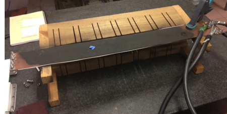
Figure 5: Painted conductor to measure temperature
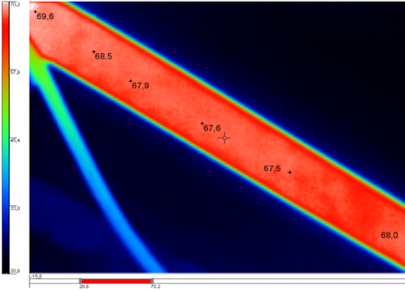
Figure 6: Temperature rise measured with IR camera
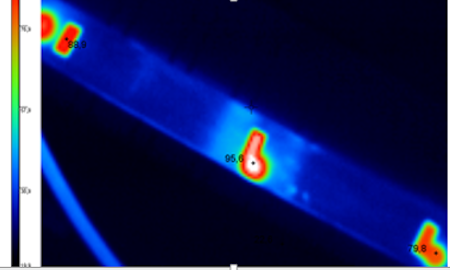
Figure 7: Not painted conductor (only with local tapes)
The temperature rise with the conductor completely painted is 44°C (Figure 2).
When this test is done with bare copper (only tape in measurement points) the temperature rises to 70°C, meaning an additional temperature increase of 26°C or 60%. Spraying a bare conductor is equivalent to putting insulation onto the conductor (emissivity ε of insulation is high). This means that moving from a stacked or "easy" busbar with non-insulated copper to a laminated "performance" busbar has a consequently significant impact on the conductor temperatures.
Contrary to what is intuitively assumed, that putting an additional insulation will increase the busbar temperature (see conduction with 0,66°C temperature rise over a 0,44mm insulation layer), the radiation effect however results in a 40% lower temperature (minus 26°C).
The impact of radiation on the thermal behavior of the busbar will reduce once the cooling is forced by a fan, as the convection is dominant. This is why naturally cooled heatsinks will always be sprayed black (impact radiation), while heatsinks with forced fan cooling will be often in uncoated aluminum.
Do you have any question or require some information about our busbars? Please contact us, if you need assistance.
Published on Nov 15, 2021