Published
Advanced Electronics Solutions
A data sheet is the main source of information for design engineers to understand the overall performance of a power module. Particularly, in this blog, we are interested in understanding its thermal performance. However, a data sheet is a difficult document to comprehend. It provides a wide variety of values and diagrams but detailed background explanations on each parameter are often missing. Design engineers have to understand the specific test set-up that has been used to determine the data sheet values. On one hand, different suppliers may not all use the same test set-up so it is difficult to compare the values. On the other hand, a test set up cannot cover all possible applications or operating conditions and the values can vary according to the user's particular application.
Is the thermal resistance value given from chip junction to case or to ambient?
In a typical power electronics application, the thermal resistance can be divided into thermal conduction from the chip junction to the heat sink and thermal convection from the heat sink to the ambient environment.
A data sheet of a power module should always indicate a value for thermal resistance. However, for most of the modules with and without baseplate, the thermal resistance will be given from junction to case (Rth,j-c) as the module manufacturer cannot guarantee a value for the complete thermal path from junction to ambient. First, he does not know how the end user will mount the module on the heat sink and so cannot define the thermal resistance for the case to heat sink transition (Rth,c-h). Second, he does not know the dimension and geometry of the heat sink. Third, he does not know which coolant will be used and under which conditions. So he cannot indicate a value for the thermal convection between the heat sink and the ambient (Rth,h-a). However, please note that the module manufacturer should make a reference to the test set-up that was used to determine the thermal resistance value given in the data sheet. If there is no such reference in the data sheet, you may find such information in applications notes.
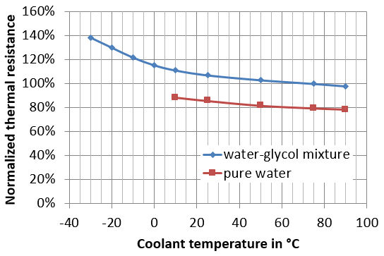
This is different for modules with integrated heat sink. In this case, the module manufacturer can indicate a value from junction-to-ambient for a specific coolant and under specific test conditions. For liquid cooled modules, minimum information regarding the test set-up should include the nature of the coolant, the coolant temperature and the volume flow. Simulation results with SiC chips on a standard test layout have been plotted in the diagram below. They clearly show that thermal resistance depends on the nature of the coolant and of the coolant temperature.
Generally speaking, the module with the lowest junction-to-case thermal resistance does not lead to the lowest junction to ambient value. Besides, the conduction term will decrease as you improve the convection term. A better heat transfer to the ambient environment is reducing the heat spreading effect in the stack of material underneath the chips.
Thermal resistance depends on materials intrinsic properties and geometry of the materials
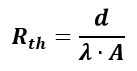
Thermal resistance is given in K/W and depends on the thermal conductivity (λ) of the materials used in the power module, on the layer thickness (d) of each material and on the heat transporting area (A). Thin layers of materials with high thermal conductivity are favorable to achieve a low thermal resistance. A larger area means lower resistance. However, due to heat spreading effect, doubling the chip area does not lead to a reduction by half of the thermal resistance.
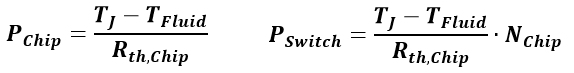
Design engineers should always check for which area the thermal resistance value is given in the data sheet. This value may be given for one chip or for one switch. Unfortunately, the data sheet may not indicate what the chip area used for the test was and how many chips were used for one switch. Besides, the chip area and number of chips per switch are likely to vary from one to another module. Unless you tear down a module and do some kind of reverse engineering, it is almost impossible to compare the thermal performance of different modules with only a data sheet.
Sometimes, for instance in technical papers or articles, thermal resistance is also given per unit area in K.m²/W. This way, a theoretical comparison of the materials used in different modules is possible but this does not tell you much about the behavior of the different modules in a real application.
Module performance vs. design to cost
Power modules are designed to deliver the highest electrical output power for the lowest cost. For a given semi-conductor technology in operation at a specified voltage, higher electrical output power is achieved with higher load current. The result is an increase of the waste heat. As a consequence, chips are operated at higher temperature and ultimately this can lead to reliability issues.
Using multiple chips in parallel in one switch helps to avoid such reliability issues and achieve the required electrical output power. Here again, doubling the chip area does not lead to an increase by 50% of the output power. This can be explained by effects like thermal coupling between chips and limited heat spreading. Total chip area relative to substrate area and chip position relative to other chips and to substrate border are important design considerations that impact the thermal performance of the module. Besides, using multiple chips in parallel has a significant impact on cost and it may be less expensive to use larger substrates or substrates with thinner, higher performing materials.
In a nutshell, you need much more information than just a data sheet to make a good assessment on the thermal performance of the selected power module in your application. Module manufacturers provide assistance to their customers and end users (e.g., in the form of applications notes). As a manufacturer of metallized ceramic substrates and as a development partner, Rogers’ Power Electronics Solutions experts are available to help, too. Do you have any design questions or require some assistance with the selection of a suitable substrate or cooler for your application? Please contact us if you have any questions.
Related Products:
curamik Ceramic Substrates, curamik Cooling Solutions
Tags:
Automotive & EV/HEV, Aerospace & Defense, General Industrial, Wind & Solar, Wired Infrastructure
Published on Nov 01, 2018