
The Optimizing PCB Designs Guidebook offers insights into innovative materials, fabrication techniques, and design considerations that enhance circuit performance.

Paris provided more energy to the 2024 Olympic Games from renewable energy sources than ever before. Rogers Corporation offers material solutions that increase the performance of state-of-the-art applications.
This paper was presented at SPIE Photonics West 2024 in San Francisco, CA. It was authored by J. Wiesend, F. Wagle, and S. Lutter.
Check out the six-part Coonrod's Corner video series and eBook designed to help RF engineers adapt education to real-world application design.

The Rogers Design Support Hub and Technology Support Hub have long served as valuable tools for our customers. We are happy to announce these hubs are now fully mobile-friendly.

With Rogers’ RF microwave laminates, circuit designers and fabricators can count on the accuracy and precision of key parameters such as Dk to find the low-loss formula for their application.

A lot of thinking goes into photovoltaic systems, how to store generated energy and how to generate more energy using smaller and smaller areas. In this blog, we present two possible solutions that could be used to support renewables better in the future.
Market Development Manager Guillem Gargallo discusses a series of simulation tools that help customers and support in the decision making to select the optimal substrate for their application.
Ceramic substrates are materials typically used in Power Modules with unique thermal, mechanical and electrical properties that make them ideal for demanding power electronics applications.

Modern circuit designers are faced with integration and miniaturization, trying to pack as many functions into the smallest PCB possible. Technical expert John Coonrod offers his take on how not to get lost in the layers.
How would Rogers’ Micro-Channel-Coolers perform in air cooling applications?
Thermal management is one of the key aspects of electrical system design, as it has a direct link to the reliability and lifetime of the system, both short and long term.

Measurements and methods to determine dielectric constant (Dk or relative permittivity) are essential for characterizing a circuit laminate as part of a circuit design process. But many different Dk test methods have emerged and evolved over the years, often yielding different results for the same material.
As LED types changed from a T-Pack to Chip on Board packaging technology and an overall reduction in size, the number of LEDs per array tremendously increased. This results in a higher heat density and heat load which increases the challenges in cooling the package.
This is the second blog of a two-part series which addresses considerations that can be important to understand for a RF designer, when transitioning from designs at lower frequency to designs at much higher frequencies, millimeter-wave frequencies.
A new Si3N4 raw ceramic material is now available, and Rogers will leverage its strong partner network to deliver large-scale production of higher performing Si3N4 AMB substrates.
During the past years, electric automobiles have evolved from conceptual prototypes to a booming trend, overcoming great challenges on the way and occupying a growing portion of the automotive market. E-aircrafts are now in the concept phase, getting ready to take off.
This blog is part one of a two-part series which addresses the transition for RF design considerations at lower frequencies to design considerations at mmWave frequencies, from a basic RF design perspective.
As millimeter-wave technologies continue to advance in the printed circuit board (PCB) industry, there are emerging needs for more diverse circuit constructions. A previous limiting factor for complex millimeter-wave PCB constructions, had been appropriate bonding materials to accommodate the circuit fabrication as well as the demanding RF performance at these high frequencies. These issues have been addressed in the following blog.
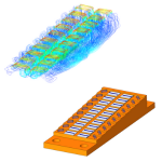
In 2004, and even some time before the global PC gaming boom started, curamik® engineers from the field of high power laser cooler applications came up with the idea to use our unique Direct Bonded Copper (DBC) technology and developed special micro channel cold plates for CPU cooling.
Silicon carbide (SiC) has outstanding properties which makes it a very useful material for power semiconductor devices in multiple applications, such as renewable energy systems and inverters for electric vehicles. However, the specific costs ($/cm²) of SiC devices are and will remain higher than silicon (Si) devices, though the cost ratio may change in the future.

Yesterday, NASA announced yet another historic moment on Mars: the landing of their most advanced explorer yet, the Perseverance Rover. After a 6-1/2 month long journey from Florida, the rover successfully touched down at the Jezero Crater at 3:55 pm EST.
Stray inductance of switching circuits is one of the most critical parameters in the design of power electronics and is becoming even more important for systems using wide-bandgap semiconductors, such as SiC and GaN.
About two decades ago, engineers in the field of laser technique were looking for a partner to design and build high power coldplates that could support their need for a cutting-edge cooling system targeted to their laser bars. Together with the curamik® engineering team the idea of bonded micro-channel-coolers was born.
Dielectric constant is the first number most engineers consider when sorting through different printed-circuit-board (PCB) materials. But what does dielectric constant really mean? And how can it affect a design if it is not “the right” dielectric constant?
Among other measures, voltage, current and mission profile are critical parameters to consider in the selection of the substrate for a given application. In this blog, we look at common applications for multi-chip power modules to understand the rationale behind each technology.
Introducing the newest version of the Microwave Impedance Calculator from Rogers’ Advanced Connectivity Solutions.
The motor, battery and electrical control system are known as the tri-electric system of e-Mobility.
Solder mask is an often-overlooked component of an RF/microwave printed-circuit board (PCB). It provides protection for a circuit but can also have an effect on final performance, especially at higher frequencies.
Circuit designers must often select a circuit technology, such as microstrip or grounded coplanar waveguide (GCPW) circuitry, with a particular design and circuit material to achieve optimum performance.
During the design phase of a power module, engineers select the components, materials and manufacturing technologies to fulfill the requirements regarding performance, reliability and costs set by their customers. Over-engineering can be desirable when safety, reliability and performance are critical.
High-frequency circuit designers must often consider the performance limits, physical dimensions, and even the power levels of a particular design when deciding upon an optimum printed-circuit-board (PCB) material for that design.
In this edition we would like to answer a few frequently asked questions to benefit those new to the power electronics community and a refresher training for those experienced in the industry as well.
Aerospace & Defense, Automotive & EV/HEV, General Industrial, Major Appliances, Rail, Wind & Solar

As our industry adapts to the evolving tradeshow landscape, many events have transitioned their “brick-and-mortar” presence to virtual trade show experiences as a way to connect industry participants in a socially distant world. Virtual shows and events are a viable and cost-effective option to generate additional engagement when traditional shows are not practical.
In a previous blog, we examined the current collector busbars for the cylindrical cell in electric vehicles. Many of the electrical, mechanical and thermal requirements are also applicable to prismatic cells. However, the manner in which a battery pack in the vehicle is designed depends on the OEM´s preference.
During this time of uncertainty due to the coronavirus pandemic, we greatly appreciate the strong relationships that have been built over the last decades. We are focused and working hard to ensure that we continue to serve you through this evolving situation.
The copper grain size is an important property of Direct Bonded Copper (DBC) substrates. Variations in the copper grain size cannot be fully excluded, but large variations may affect the subsequent assembly processes or the performance of DBC substrates. Module manufacturers can rely on the experience and competence of Rogers' Power Electronics Solutions team to deliver substrates with a consistent grain size.
Aerospace & Defense, General Industrial, Major Appliances, Rail, Wind & Solar
Thermal management is a challenge that the correct busbar can assist with, especially for cylindrical cell connections where the busbar may connect hundreds of cells to make a complete module.
Direct Bonded Copper (DBC) and Active Metal Brazed (AMB) substrates have been available for the last four decades. Together they have made a large contribution to the market adoption and penetration of power modules.
Aerospace & Defense, Automotive & EV/HEV, General Industrial, Major Appliances, Rail, Wind & Solar
The beginning of a new year is a time for resolutions. It is also a perfect opportunity to discuss key principles to design custom Direct Bonded Copper (DBC) and Active Metal Brazed (AMB) substrates.
Aerospace & Defense, Automotive & EV/HEV, General Industrial, Major Appliances, Wind & Solar
Information on ROLINX CapLink solutions: a complete integration of a laminated busbar and discrete film capacitor.
In today's blog you will find an interview with Sebastiaan De Boodt, who works for Rogers Corporation.
Aerospace & Defense, Automotive & EV/HEV, General Industrial, Rail, Wind & Solar
Olivier Mathieu talks about the design, internal structure and thermal performance of our micro channel liquid coolers.
Aerospace & Defense, General Industrial, Wired Infrastructure

Circuit materials used in 5G Microwave and mmWave amps are subject to more requirements than ever before.
In the last decade power electronics has gained importance with climate targets set to cut greenhouse gas emissions; therefore increasing renewable energy consumption. The new generation is aware of the environment and pollution challenges that our society is facing, motivating and attracting young engineers to study power electronics.
Aerospace & Defense, Automotive & EV/HEV, General Industrial, Major Appliances, Rail, Wind & Solar
While silicon is the most common element used for power semiconductors, copper is the most popular choice for conductor traces on printed circuit boards (PCBs) and ceramic substrates due to its electrical conductivity.
Aerospace & Defense, Automotive & EV/HEV, General Industrial, Major Appliances, Rail

At Rogers Corporation a large part of our culture is our dedication to safety, in both the workplace and our environment. Many of our products enable safety-related applications, embodying the “protect” aspect of our commitment to help power, protect and connect our world.
Electronic systems rely on efficient combination and distribution of voltages and currents from different sources. In high-power applications, such as industrial drives, renewable energy inverters, powertrains for electric vehicles and converters used in rail, energy must be channeled with minimal power losses.
Automotive & EV/HEV, General Industrial, Rail, Wind & Solar, Wired Infrastructure
In a recent Olivier’s Twist blog, the topic of Silicon Carbide semiconductor materials was discussed for future high power efficiency applications. There is also another semiconductor technology that is filling a gap in performance between Silicon and Silicon Carbide, and that is Gallium Nitride.
Dominik Pawlik explains the details about laminated busbars, the advantages and where the busbars are used.
Aerospace & Defense, Automotive & EV/HEV, General Industrial, Rail, Wind & Solar
There is currently a lot of interest for silicon carbide (SiC) as a semiconductor material because its properties make it more promising than silicon for power electronics applications.
Automotive & EV/HEV, General Industrial, Rail, Wind & Solar, Wired Infrastructure
A Quick Introduction to ROLINX® Laminated Busbar Solutions, Dominik Pawlik explains the details about laminated busbars, the advantages and where the busbars are used.
Aerospace & Defense, Automotive & EV/HEV, General Industrial, Rail, Wind & Solar

In January of 2004, the Mars Opportunity Rover began its mission in the Meridiani Planum region of Mars after a 7 month long journey from its launch in Florida. Originally intended to collect data for 90 days and travel only 1000 meters, Opportunity persevered, completing its mission 15 years and 45 kilometers later.
Josh Goldberg takes you to the floor of the 2019 Consumer Electronics Show in Las Vegas to take a closer look at some of the technologies that will soon be entering our lives.
In the world of electronics, heat can severely shorten the lifetime of a device. It is therefore necessary to move heat away from vital components such as chips, LEDs, and inverters to maintain optimal performance without shortening the lifetime. There are many different thermal management techniques that can be utilized by engineers depending on the devices heat density, space constraints and cost.
Aerospace & Defense, General Industrial, Portable Electronics, Wired Infrastructure
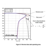
A data sheet is the main source of information for design engineers to understand the overall performance of a power module. It provides a wide variety of values and diagrams but detailed background explanations on each parameter are often missing. On the other hand, a test set up cannot cover all possible applications or operating conditions and the values can vary according to the user's particular application.
Automotive & EV/HEV, Aerospace & Defense, General Industrial, Wind & Solar, Wired Infrastructure
I recently participated in the Battery Show in Novi, Michigan where I gave a presentation during the conference on the connection of the battery cell for electric vehicles (EV). For those of you who could not attend, here is a short summary and my observations on this subject.

Choosing a high frequency circuit board material often requires weighing several factors, including cost and performance. A key starting point in sorting through printed circuit board (PCB) materials is usually the dielectric constant, or Dk, one of the essential characteristics of a laminate material and one that is subject to many comparisons among different suppliers of PCB materials.
Who cares about flatness? Process and application engineers do! These are not flattering words as they truly know how critical it is to understand and control the shape of one’s substrate, base plate and heat sink in order to achieve the best possible production yield and module performance. In this blog, I want to share with you some information about flatness that you may wish to consider as you design or use power modules.
Aerospace & Defense, Automotive & EV/HEV, General Industrial, Major Appliances, Rail, Wind & Solar
Design engineers are selecting Direct Bonded Copper (DBC) and Active Metal Brazed (AMB) substrates as circuit material for bare semiconductor chips in their power modules as they efficiently dissipate the waste heat from the semiconductors and increase the lifetime of the modules. In this blog, we explain the production process for power modules and highlight the most important characteristics of the substrates at each step of this assembly process.
Aerospace & Defense, Automotive & EV/HEV, General Industrial, Major Appliances, Rail, Wind & Solar
The MWI-2017 Microwave Impedance Calculator software doesn’t replace sophisticated suites of modeling tools, such as the Advanced Design System (ADS) from Agilent Technologies or Microwave Office from AWR. Nor can it challenge the prediction capabilities of a planar or 3D electromagnetic (EM) simulator such as HFSS from Ansys or the Sonnet suites from Sonnet Software. But what it does, it does well, which is to calculate key parameters for most common microwave transmission lines, including microstrip, stripline, and coplanar-waveguide transmission lines.
Nowadays the requirements for high power density, increased reliability and low inductance are not only important for busbars but also for complete inverter design. In higher-power applications such as traction, solar and wind inverters and the powertrains of electric vehicles (EVs) and hybrid electric vehicles (HEVs), energy must be channeled with minimal combining and distribution loss.
Thermal management is required to achieve optimal power electronic system performance and reliability. While in operation, power semiconductor devices generate a lot of waste heat as a result of conductive and switching losses. This heat has to be dissipated from the semiconductor junction to the semiconductor package and ultimately to the ambient environment to prevent thermal runaway.

By 2020, experts project that 50 billion connected devices will be in use globally. The Internet of Things (IoT), smart homes, connected cars, fitness monitors and other emerging technologies are increasingly relying on global wireless networks to connect.

A global push to reduce CO2 emissions, as well as government incentives and consumer demand, is leading the world’s largest automotive manufacturers to accelerate plans to introduce all-electric and hybrid-electric (EV/HEV) models.
As a design engineer for power electronics systems, you require the selected power module to fulfill its electrical function as described in its data sheet and you expect this module to be reliable meaning that it should operate under given conditions, in a defined period of time and within an acceptable failure rate.
Aerospace & Defense, Automotive & EV/HEV, General Industrial, Major Appliances, Rail, Wind & Solar

Millimeter-wave frequency bands hold valuable spectrum for what lies ahead: fifth-generation (5G) wireless communications and automotive collision-avoidance radar systems. Signals at 60 GHz and higher might have once been thought too high to transmit and receive with affordable circuits. But semiconductor devices and circuit technologies have improved in recent years and millimeter-wave circuits are becoming standard electronic equipment in many car models.

This year marks the 50th Anniversary of Rogers ACS operations in Chandler, AZ, and represents Rogers 50th year as part of the Chandler business community. Join us to celebrate our shared history and success!
Filter and antenna designers have long appreciated the benefits of designing distributed high-frequency circuits using defected ground structure (DGS) layouts with different types of circuit materials. As the name suggests, a DGS is a circuit in which an intentional defect or interruption has been formed in the ground plane to realize distributed forms of passive circuit elements, such as capacitors and inductors.
Much of the buzz on the show floor at the 2017 IMS in Honolulu was about millimeter-wave devices and circuits. At one time, frequencies above 30 GHz were considered “exotic” and only for military or scientific applications. But times have changed, and available spectrum is scarce.
Power electronics is changing rapidly. New packaging technologies are facing a rise in chip temperatures as seen in such applications as EVs / HEVs. Electronics increasingly need longer lifetimes to function in harsh conditions, such as wind turbines.
Printed circuits for high-speed and high-frequency applications rely on fine-featured transmission lines for signal transmission. Three of the most commonly used transmission-line technologies for these applications are microstrip, stripline, and grounded coplanar-waveguide (GCPW) transmission lines.
You think the pace of technology innovation is fast now, wait til you see what’s going to happen with 5G wireless. 5G will drive an Internet of Things (IoT) ecosystem of intelligent, fully connected sensors and devices, capable of improving economies small and large, and further blurring geographical borders.
As electronic devices continue to shrink in size and increase in power, demand grows for power electronic circuits with higher power density. Increased operating temperatures are one of the tradeoffs of higher circuit power density, resulting in an increase in thermal stress for the circuit materials that serve as substrates for modern power electronic circuits. New processes and materials are available to address these challenges.
Growing demand for mobile wireless communications services has quickly eclipsed the capabilities of Fourth Generation (4G) Long Term Evolution (LTE) wireless networks and created a need for a next-generation mobile wireless network solution. Fifth Generation (5G) wireless networks promise more capacity and capability than 4G LTE systems, using wider channel bandwidths, new antenna and modulation technologies, and higher carrier frequencies even through millimeter wave frequencies. But before 5G wireless networks can become a reality, systems and circuits will be needed for higher frequencies than current 2.6-GHz 4G LTE wireless networks.
Woven glass is incorporated into printed-circuit-board (PCB) materials to provide structural strength. It aids the mechanical stability of a laminate, but what does it do to its electrical behavior? One of the classic concerns regarding woven glass reinforced laminate PCBs is that the “glass weave effect” can have negative impact on the electrical performance of high-speed or high-frequency circuits fabricated on these laminates. In this blog post, we examine some of the factors affecting the glass weave effect phenomenon.